Technical overview of CNC/PLC bridge saw architecture, components, and setup. Repeatability up to ±0.05mm.
For engineers, understanding a machine goes beyond its output. It's about how the architectural choices directly influence performance metrics like accuracy, uptime, and safety. A CNC bridge saw is a system of interconnected components, each playing a critical role in its overall capability. The workflow, from loading a program to the final cut, is a sequence orchestrated by these components working in concert.
This article breaks down the technical principles of a modern CNC bridge saw, from its structural design to the typical parameter ranges of its key components. Analyzing these elements provides the foundation for effective operation, troubleshooting, and integration.
Request an engineer walkthrough of the Bridge Saw Architecture

CNC Bridge Saw Structure and Control
Structurally, a CNC stone bridge saw consists of a rigid bridge gantry that moves over a stationary worktable. The core cutting mechanism includes a high-power spindle fitted with a diamond blade. This entire assembly is driven by servo motors along high-precision linear guides to ensure accuracy. The system is controlled by an industrial computer (a PLC or full CNC controller) via a Human-Machine Interface (HMI), and utilizes sensors, a coolant loop, and a safety enclosure to function reliably.
The machine achieves its purpose through coordinated multi-axis motion, executing G-code programs to perform straight cuts, miters, or complex contours. Its precision is a key attribute, with repeatability capable of reaching ±0.05mm (manufacturer-reported).
- Core Modules: Gantry frame, spindle/blade assembly, axes/drives, HMI/PLC/CNC controller, sensors, coolant loop, and safety enclosure.
- Supported Axes: Standard X (gantry travel), Y (bridge travel), and Z (vertical depth), with optional rotation (A/C-axis) and tilting (B-axis) for advanced cuts.
- Data & Programs: Operates on programs typically imported from CAD/CAM software (e.g., DXF files) and allows for recipe management for different materials.
System Overview and Precision up to ±0.05mm
The architecture of a CNC bridge saw is designed for rigidity and precision. Each module contributes to the final performance:
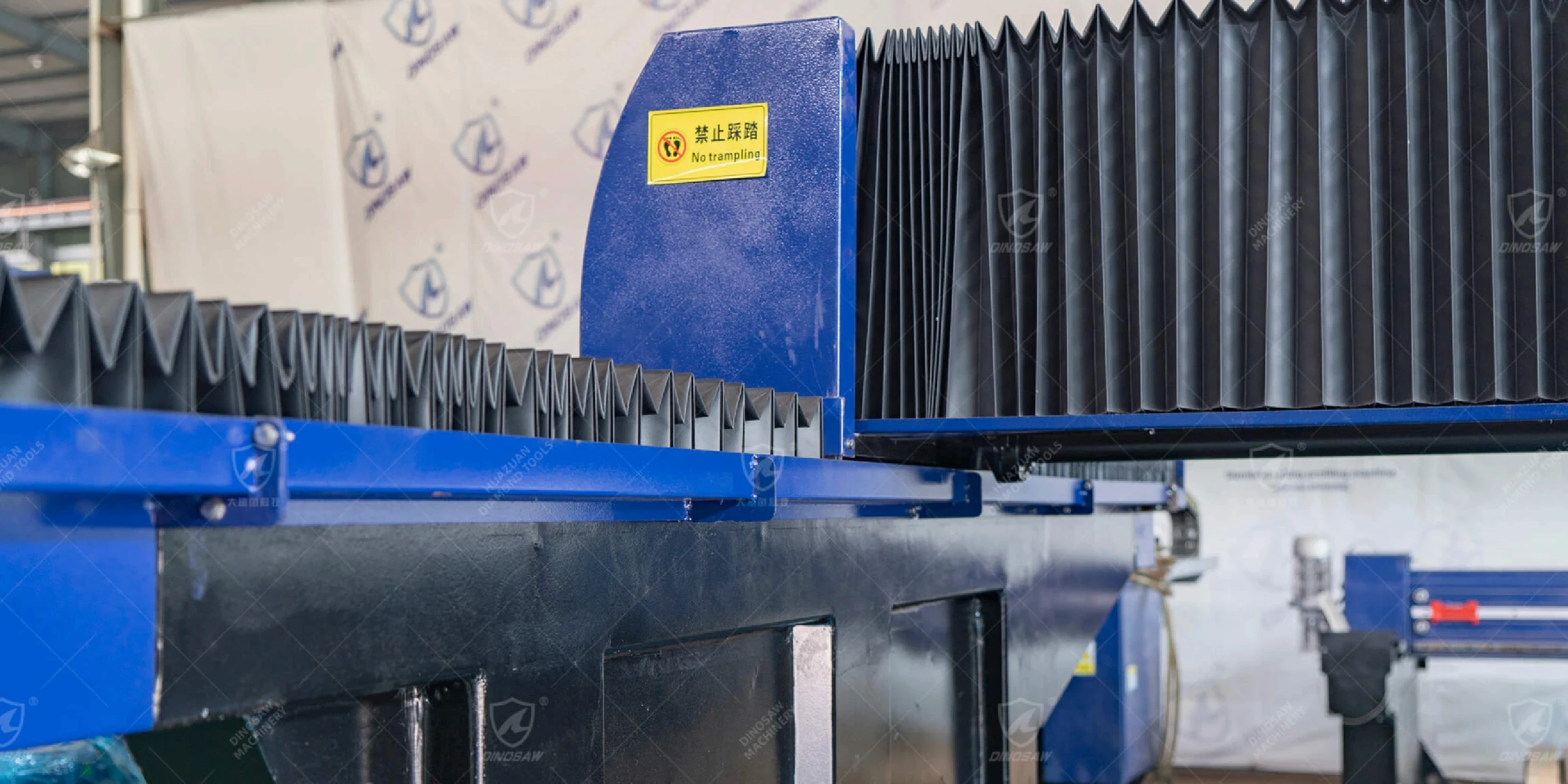
- Gantry: The bridge structure that spans the worktable. Its mass and stiffness are critical for resisting vibration (chatter) and ensuring straight, accurate cuts.
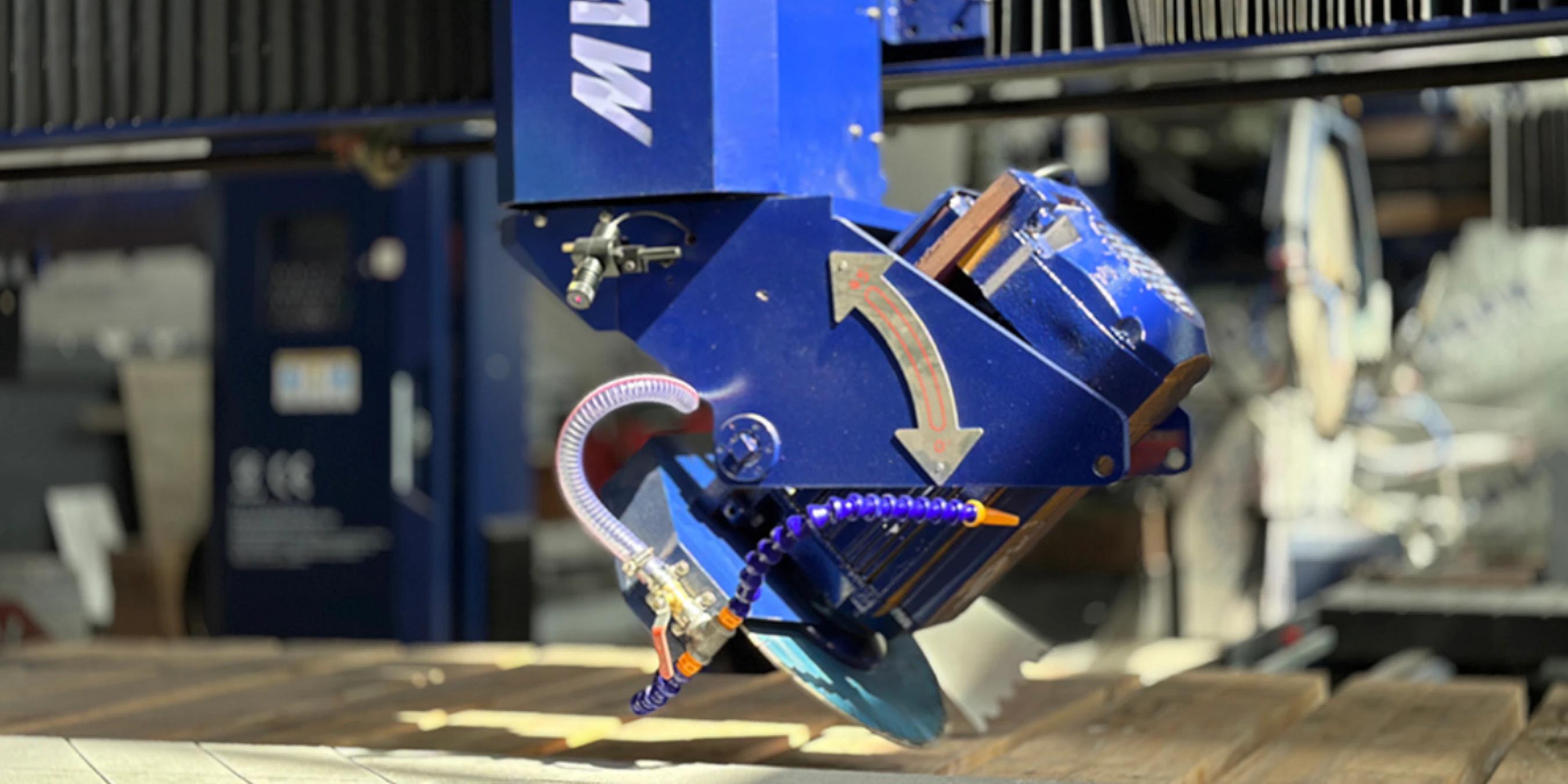
- Spindle & Blade: The heart of the cutting operation. The spindle motor provides the power and rotational speed, while the diamond blade performs the cut.
- Drives & Linear Guides: Servo or stepper motors drive the movement along each axis (X, Y, Z, etc.). They move along high-precision linear guides and ball screws to ensure smooth, repeatable motion.
- HMI/PLC(CNC optional): The Human-Machine Interface (HMI) is the operator's control panel. The Programmable Logic Controller (PLC) is the industrial computer that reads the G-code and executes the commands, controlling the motors and other peripherals.
- Sensors: Various sensors monitor the system, including encoders for positional feedback, and optional sensors for tool wear, vibration, and coolant flow/temperature.
- Coolant Loop: A closed- or open-loop system that delivers water to the blade/stone interface. This cools the blade, prevents thermal damage to the stone, and flushes away cutting debris.
- Enclosure & Safety: Safety interlocks, light curtains, and physical guarding that protect the operator from moving parts and water spray.
Key Components of a Stone Bridge Saw
- Spindle Power & RPM: Typically ranges from 15 kW to 22 kW. RPM is tuned to blade diameter and material hardness; consult your vendor's datasheet.
- Feed Rate: Varies based on material hardness and depth of cut. Always begin with conservative settings recommended by your vendor.
- Positioning Repeatability: A critical metric for precision. DINOSAW saws can achieve high precision up to ±0.05mm (per manufacturer specifications).
- Coolant Flow: Generally 3-5 m³/h to ensure adequate cooling and debris removal.
- Blade Diameter & Kerf: Blade diameters can range from 400mm to 800mm, with the kerf (cut width) being a critical factor in material waste calculations.
- Servo P-I-D Bands: The proportional, integral, and derivative settings in the servo drives that are tuned to optimize response time versus overshoot, affecting both speed and accuracy.
Failure Modes and Mitigations
- Blade Glazing: Symptom: The blade stops cutting effectively and may produce burn marks. Mitigation: Check coolant flow and concentration; dress the blade with a abrasive block; adjust feed rate/RPM.
- Chatter/Vibration: Symptom: A wavy or chipped finish on the cut edge. Mitigation: Check for loose blade flanges, worn spindle bearings, or improper feed/speed settings. May require servo retuning.
- Thermal Drift: Symptom: Loss of dimensional accuracy over a long cutting job. Mitigation: Implement a machine warm-up cycle to allow components to reach thermal stability.
- HMI Mis-entry: Symptom: Incorrect machine movements or program errors. Mitigation: Implement tiered user permission levels in the HMI to restrict access to critical settings.
Connectivity with Factory Systems
For integration into a modern factory, a CNC bridge saw must communicate with other systems. Key compatibility features include:
- Industrial Protocols: Support for standards like OPC UA, Profinet, or Modbus for communication with a central factory management system.
- Fixture I/O Mapping: Digital inputs and outputs for integrating with automated clamping, vacuum tables, or robotic loading systems.
- Recipe Import/Export: The ability to import cutting programs from CAD/CAM software (e.g., DXF files) and export production data, often in CSV or JSON formats.
Starting Settings for Common Materials
While optimal settings require testing, these are common starting points:
- Granite: Higher spindle power, lower feed rate. RPM/feed should be tuned to blade diameter and material hardness; begin with conservative vendor-recommended settings. Coolant: High flow.
- Marble: Prone to chipping; requires a specific blade bond. Tune RPM/feed to material; begin with conservative settings. Coolant: Medium flow.
- Quartz/Engineered Stone: Consistent material but can be abrasive. Tune RPM/feed to blade and material; begin with conservative settings. Coolant: High flow.
FAQs: Technical Questions
What repeatability can a CNC bridge saw achieve for granite?
For a high-quality bridge saw with precision linear guides and servo motors with encoders, repeatability of ±0.05mm to ±0.1mm is a realistic and achievable specification for most applications.
Can a CNC bridge saw integrate with factory software?
Integration may be possible if the machine exposes compatible industrial data interfaces; verify details with your vendor and software provider.
What’s the training curve for maintenance teams?
For staff with a background in industrial machinery, the training curve focuses on the specifics of the CNC control, servo tuning, and stone-cutting application. A typical training period would be 1-2 weeks for full competency.
How to size coolant on a granite bridge saw?
Coolant flow recommendations depend on blade diameter and material, but a typical range is 3-5 m³/h per blade. Always check your vendor’s specifications.


 中文
中文 한국어
한국어 Sep 15, 20253 MIN READ
 English