


 中文
中文 한국어
한국어Ms.Lizzy
Hi, this is Lizzy from Dinosaw ( Not a Robot ). Which Machine ( model ) do you want? Please WhatsApp us now
Open Hours:8:30am-20:30pm
WhatsApp: +86 198-5901-3937
 Sep 19, 20255 MIN READ
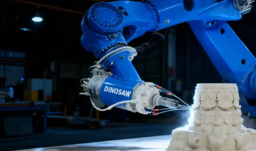 Sep 19, 20255 MIN READ
A technical breakdown of the DINOSAW 7-axis robotic stone carving cell. Explore its architecture, core components, operational parameters, and failure mitigation for granite, marble, and limestone. Achieves ±0.06 mm repeatability.
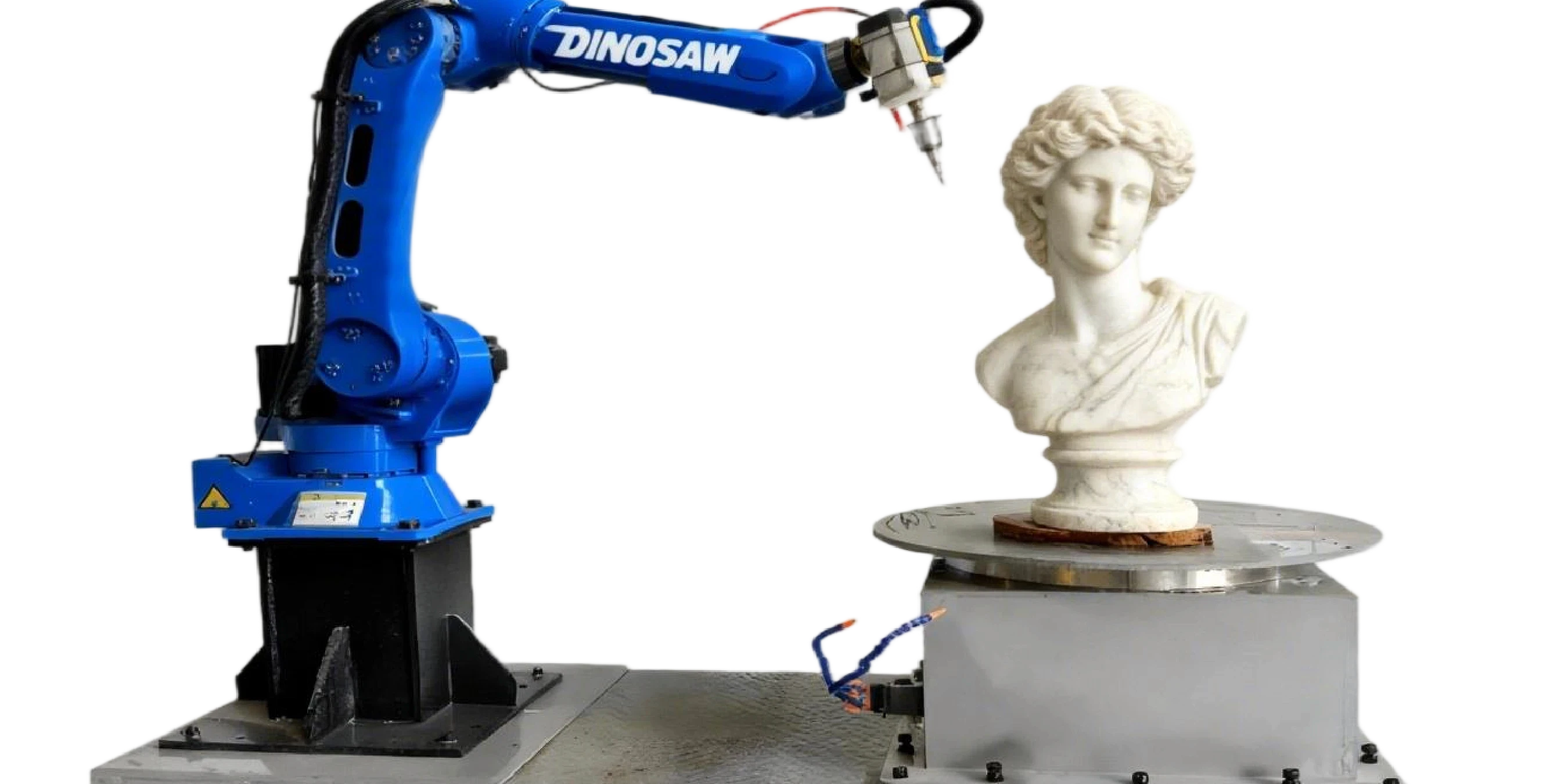
Stone carving in granite, marble, and limestone pushes mechanical limits—precision, rigidity, and dust/slurry control. A 7-axis robotic stone carving cell (6-axis robot + rotary table + water-cooled spindle) delivers repeatability (±0.06 mm, manufacturer-reported), safer operations, and predictable cycle times.
See the Dinosaw robotic stone carving for the reference architecture powered by diamond tools.
Need to match these technical specs to your production floor? Our engineers can provide a detailed integration plan.
The cell's performance is built on the seamless interaction of four pillars: mechanics, controls, software, and safety. A typical workflow starts with a 3D scan or CAD model, which is imported into the CAM software to generate a multi-axis toolpath. This program is then sent to the robot controller, which executes the complex, synchronized movements required for carving.
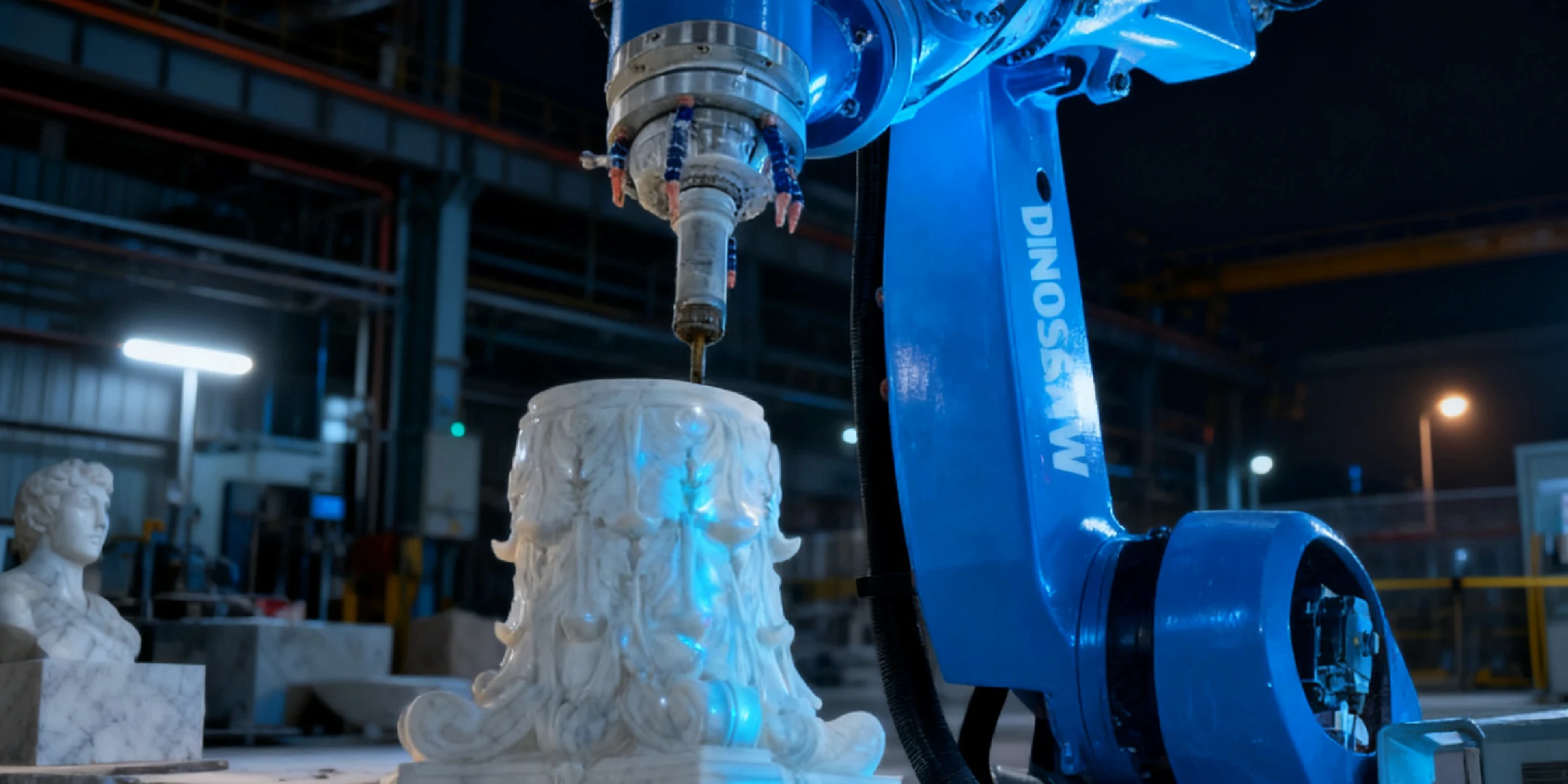
Each component within the stone robot cell has a defined operating range. Understanding these parameters—from the water-cooled spindle for carving system to the specific DINOSAW diamond tooling—is crucial for process optimization and troubleshooting.
| Component | Key Parameters & Typical Ranges |
|---|---|
| Water-Cooled Spindle | Speed: 6,000–24,000 RPM; Torque: Nm at various RPMs; Coolant Flow: 5–15 L/min (1.3–4.0 gpm) |
| DINOSAW Diamond Tools | Shank Sizes: 6 mm, 8 mm, 12 mm ; Tool Families: Ball-nose/flat-end mills, tapered engraving bits, V-groove bits, burrs. |
| Rotary Table (7th Axis) | Diameter: diameter matched to max block size (confirm during fixture design), mm/in; Max Load: load capacity selected to your heaviest block (confirm during mechanical design), kg. |
| Vision/Scanning System | Resolution: Scanner resolution varies by model (confirm with vendor), mm point spacing. |
Proactive maintenance and an understanding of failure modes are essential for maximizing uptime in a high-wear stone carving environment.
A robotic cell does not operate in isolation. Its ability to communicate with other factory systems and accept standard data formats is key to its utility.
The following tables provide conservative starting points for carving different types of stone. These must be refined based on the specific machine, tool, and material batch.
| Process | Tool | Spindle Speed (RPM) | Feed Rate (mm/min) | Step-Over |
|---|---|---|---|---|
| Roughing | DINOSAW Ball-Nose Mill | 8,000–12,000 | 1,000–2,000 | 40-50% of tool diameter |
| Finishing/Lettering | DINOSAW V-Groove Bit | 15,000–20,000 | 500–1,000 | N/A |
| Process | Tool | Spindle Speed (RPM) | Feed Rate (mm/min) | Step-Over |
|---|---|---|---|---|
| Roughing | DINOSAW Ball-Nose Mill | 10,000–15,000 | 1,500–3,000 | 50-60% of tool diameter |
| Finishing | DINOSAW Tapered Bit | 18,000–24,000 | 800–1,500 | 5-10% of tool diameter |
| Process | Tool | Spindle Speed (RPM) | Feed Rate (mm/min) | Step-Over |
|---|---|---|---|---|
| Roughing | DINOSAW Ball-Nose Mill | 12,000–18,000 | 2,500–4,000 | 50-70% of tool diameter |
| Finishing | DINOSAW Tapered Bit | 20,000–24,000 | 1,200–2,000 | 10-15% of tool diameter |
The DINOSAW 7-axis carving cell is an engineered ecosystem designed for precision and durability in stone fabrication. Its architecture—from the water-cooled spindle and DINOSAW diamond tools to the robust control system—directly mitigates common failures like vibration chatter and thermal drift. For engineers and maintenance teams, this translates to higher uptime, consistent quality, and a safer work environment. The next step is to map these technical capabilities to your specific operational needs.
A payload of load capacity selected to your heaviest block (confirm during mechanical design), kg and reach of reach sized to your largest part envelope (confirm during layout), mm/in are typical starting points. This must account for the weight of the spindle, tool changer, and the tool itself. The rotary table will have dimensions of diameter matched to max block size (confirm during fixture design), mm/in.
Plan for a table diameter matched to max block size (confirm during fixture design), mm/in with a max load capacity selected to your heaviest block (confirm during mechanical design), kg. Indexing accuracy is typically specified in arc-seconds (confirm with vendor). Ensure sufficient clearance around the table for the robot's full range of motion.
Manage spindle temperature per manufacturer guidance (cooling and temperature control). Consider a warm-up cycle and schedule critical finishing passes after thermal stabilization.
The system typically supports industrial protocols like Profinet or OPC UA for integration. Confirm specific protocol needs during the design phase. This allows for I/O mapping for peripherals (fixtures, sensors) and integration into a central safety circuit.
Typical safety practices include an emergency-stop circuit and interlocked access doors, complemented by enclosure protection (e.g., IP65) and spindle status monitoring. Consult local standards for required devices and test cadence.
Common methods include monitoring spindle load trends for increases, using software-based tool life counters to trigger a change, or integrating a laser tool-setter to automatically measure tool dimensions between cycles.
Yes. Offline Programming (OLP) software (e.g., SprutCAM) is essential for maximizing uptime, as it allows programming while the machine runs. It is also critical for simulating complex 7-axis moves to avoid collisions and converting 3D scan data into executable toolpaths.
 English
Get A Easy Solution
Chat Online
Hi, this is Lizzy from Dinosaw ( Not a Robot ). Which Machine ( model ) do you want? Please WhatsApp us now
Hello 👋 How can we help?