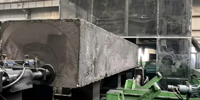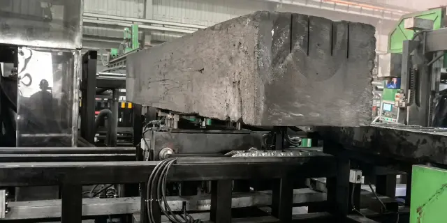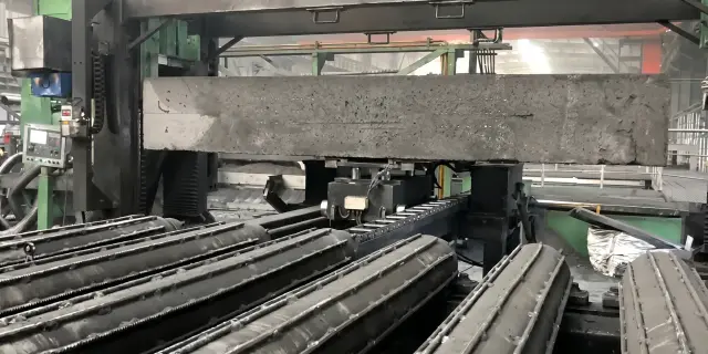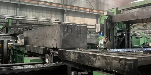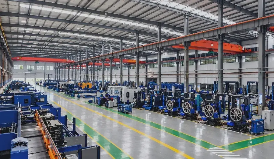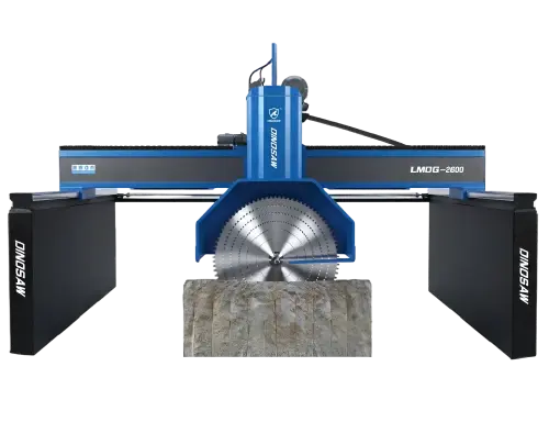
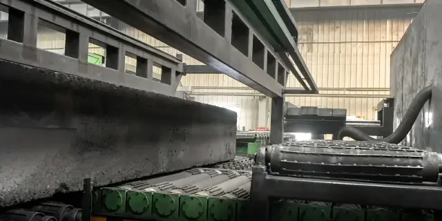
Cathode Carbon Block Machining Line

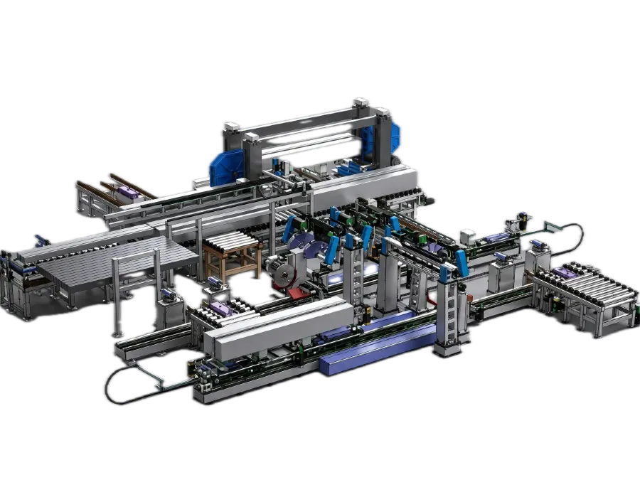
Custom-engineered for cathode carbon block trimming, slot cutting, bottom release cutting, scrap separation, and downstream line integration. In aluminum smelter cathode preparation, cutting is only the visible step. The real cost usually appears later, when raw block variation shifts groove position, bottom bridge release becomes unstable, scrap still needs manual handling, and downstream transfer no longer matches the next process. Dinosaw Machine builds cathode carbon block machining lines for these exact conditions. This cathode carbon block machining line is configured around your block size, groove layout, target throughput, dust-control requirements, and workshop interface. It combines measurement, positioning, trimming, multi-cut slot processing, bottom release cutting, scrap removal, and transfer in one coordinated workflow, making it better suited to new projects, retrofit lines, and capacity expansion than a standalone cutting machine.
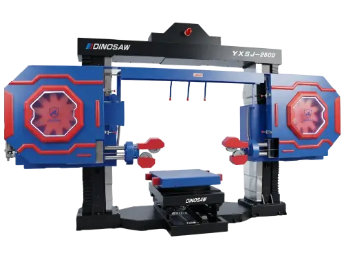
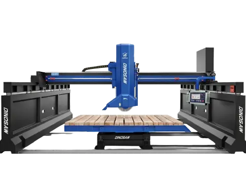
3-Station Turnkey LineBridge squaring + multi-blade slicing + wire-saw slot and groove machining
Custom EngineeredLayout, envelopes and groove logic designed around your cathode block program
Retrofit ReadyIntegrates with existing carbon-plant equipment during smelter rebuilds

Applicable Materials

Cathode carbon blocks, graphitized cathode blocks and carbon-based materials

Certifications & Credentials

CE Certified · ISO 9001:2015 · Industry Standard Drafting Participant · 120+ Countries & Regions Served

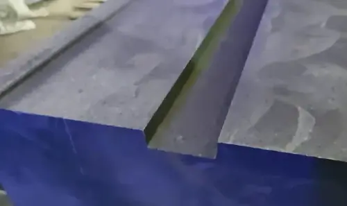
Cathode Block Workpieces & Finished Machining Output

Configured for cathode carbon blocks and graphitized workpieces. This machining line eliminates manual scrap release and slotting variations, outputting finished blocks directly ready for downstream integration.

Real Machining Performance & Key Metrics

The cathode carbon block machining line is a project-engineered system, not a catalog machine: bridge saw squaring, multi-blade slicing and diamond wire slotting are balanced as one line, with dust containment and plant integration designed around the smelter's actual potlining workflow.

3 Stations

Combined Machining Logic

Bridge saw for squaring, multi-blade station for rate-based slicing, diamond wire for narrow slots and grooves — each geometry is assigned to the cutting method best suited to it.

Custom Layout

Engineered per Smelter

The line is designed around incoming block dimensions, groove layouts and plant logistics — no standardized machine fits every carbon plant, so the line is engineered per project.

Balanced

Station-by-Station Line Design

Line capacity is balanced station by station during engineering, so no single station is sized to throttle the whole flow — the bottleneck question is answered on paper before manufacturing.

Integrated

Carbon Dust Control

Extraction and containment are designed into each cutting station from the project stage — a health, housekeeping and electrical-safety requirement in carbon plants, engineered in rather than retrofitted.

Applicable materials: Cathode carbon blocks, graphitized cathode blocks and carbon-based materials.

Typical applications: Aluminum smelter potlining preparation — squaring, slicing and slot/groove machining of incoming cathode blocks before pot assembly, and retrofit integration projects in existing carbon plants.

Line capacity and cycle times are engineered per project after block dimension and layout review.

Cathode Carbon Block Machining Line Specifications

The machining line is a project-engineered system: station count, cutting envelopes, fixture design and material flow are defined after reviewing incoming block dimensions, groove patterns, plant layout and existing equipment. Bridge saw, multi-blade and wire saw stations combine with in-line handling and dust containment — the proposal follows the survey, not a fixed specification.

Cathode carbon block projects are usually won or lost on process fit, not on a fixed size-and-power table. For that reason, this line is specified through technical standards and custom configuration scope.

Technical Standards

Networked PLC control for coordinated multi-station operation
Measurement feedback for block detection and position adjustment
Hydraulic alignment and clamping before cutting
Bridge saw, multi-blade, and wire saw stages configured around groove and release-cut requirements
Automatic position correction based on measured block data
Dust-protected electrical design for carbon and graphite processing environments
Emergency stop, guarding, and wire-break alarm/stop protection
Line design focused on stable operation, maintenance access, and workshop integration

Custom Configuration Scope

Block size range and geometry
Groove quantity, groove position, and groove layout
Target output per shift or per day
Loading, transfer, rotation, and flipping configuration
Scrap collection and discharge method
Dust extraction and enclosure strategy
Infeed and outfeed direction
Existing line connection height and interface
Preferred electrical, hydraulic, and control brands

Core Technology & Line Structure

Four engineering decisions behind the cathode block machining line. The numbered points on the line diagram correspond to the systems below.

Cathode Carbon Block Machining Line for Aluminum Smelters - Dinosaw Machine

Cathode Block Machining Workflow

A line cycle follows four steps: incoming cathode blocks enter the bridge saw for squaring, sections slice on the multi-blade station, the wire saw machines slots and grooves per the potlining layout, then finished blocks discharge for potlining — dust captured at every station.

01

Combined Station Logic

Each station cuts the geometry it cuts best: the bridge saw squares incoming blocks, the multi-blade station slices sections at rate, and the wire saw machines slots and grooves — one balanced flow instead of one machine compromising every operation.

02

Block-Family Variation Handling

The engineering model accounts for incoming block families, dimension ranges and groove layouts: fixtures and machining envelopes accommodate supplier and campaign variation, so groove positions hold accuracy across dimension spread instead of rejecting out-of-family blocks.

03

Retrofit Integration

Rebuild projects connect the line with existing machining equipment: stations integrate into current material flow, so a smelter adds capacity without demolishing a working carbon plant.

04

Carbon Dust Containment

Carbon dust is conductive, abrasive and a respiratory hazard: extraction and containment are designed at every cutting station — protecting electrical equipment, housekeeping and the work environment from day one of operation.

05

Project Engineering Model

This is not a fixed catalog machine: block dimensions, groove layouts, target campaign volume, plant space and existing assets determine the final line. The proposal starts from your data, and the line is validated against it before manufacturing.

06

Potlining-Oriented Flow

The line ends where potlining starts: finished blocks discharge in the condition the pot assembly consumes them, and the material flow between carbon plant and potroom is part of the line logic.

Turnkey Machining Line vs. Standalone Machines for Cathode Block Production

A production-model comparison for aluminum smelter carbon plants.

Turnkey Machining Line vs. Standalone Machines for Cathode Block Production
Standalone MachinesVSMachining Line
One machine compromises all operationsGeometry coverage✓ Dedicated station per geometry
Machines sized independently, flow discovered laterLine balance✓ Station capacities balanced as one project
Manual adaptation per block familyDimension variation✓ Fixtures engineered per block family
Per-machine enclosures added laterDust control✓ Containment designed line-wide
Solved after installationInterfaces✓ Mechanical/electrical interfaces engineered upfront
Isolated new equipmentRetrofit coordination✓ Layout built around existing plant assets

Note: configurations vary by brand and model; actual performance depends on the specific machine, material and working conditions.

The Manufacturer Behind the Cathode Block Line

DINOSAW is a manufacturer of CNC stone processing machinery, specializing in diamond wire saw machines and CNC stone cutting equipment. With more than 20 years of R&D and manufacturing experience, DINOSAW contributes to industry standards including T/CMES 41001-2025 for CNC wire saw machines, holds 100+ technical patents, and supplies equipment and technical support to customers in 120+ countries and regions. Its manufacturing and management systems are certified to ISO 9001, ISO 14001 and ISO 45001, with CE-compliant machinery for international markets.

DINOSAW CNC stone machinery manufacturing workshop
DINOSAW R&D & ManufacturingMechanical Design · CNC Control Development · Assembly · Testing · Commissioning · Global Delivery
Industry Standard Drafting

DINOSAW contributes to industry standards for stone machinery, including T/CMES 41001-2025 for CNC wire saw machines, as well as standards covering multi-wire saws, combined wire saw machines and five-axis bridge cutting equipment. This work reflects the company’s long-term involvement in machine design, manufacturing, testing and quality control.

20+Years of Stone Machinery R&D & Manufacturing Experience
100+Technical Patents — Covering machine structures, CNC control, cutting systems and stone processing technologies
120+Countries & Regions Served — Equipment, installation and technical support worldwide

CE Compliance & ISO Management Systems

CE: Stone cutting machinery assessed against Machinery Directive 2006/42/EC and relevant EN standards.
ISO: Management systems certified to ISO 9001, ISO 14001 and ISO 45001.

Project Requirements & After-Sales Support

DINOSAW engineers the line around the smelter's data, with installation, commissioning and documentation through the project cycle.

LayoutEngineered per plant

Plant survey and material flow study before quotation.

Power SupplyEngineered per station count

Electrical design confirmed during project engineering.

Dust ControlIntegrated extraction

Carbon dust containment engineered at every station.

01 · Pre-Shipment & DeliveryMachine configuration, packaging and transport requirements confirmed before dispatch, with factory inspection and documents verified.
02 · Installation & CommissioningOn-site utilities and foundation check, machine positioning, commissioning and acceptance.
03 · Operator TrainingHands-on training covering routine CNC operation and daily checks of blades, spindles, cooling and lubrication.
04 · After-Sales SupportRemote technical assistance, maintenance support and spare parts coordination throughout the machine's service life.

Cathode Carbon Block Machining Line FAQ

What Buyers Usually Need to Confirm Before Specifying a Cathode Block Line

A cathode carbon block machining line is a custom production line that prepares cathode blocks for the next process through measurement, trimming, slotting, bottom release cutting, scrap separation, and transfer.

  • It is mainly used in aluminum smelter cathode-block preparation and similar carbon-product machining projects.
  • The value is not one cut by itself, but a connected workflow that links positioning, machining, release cutting, scrap handling, and transfer.
  • Buyers usually start looking for this type of line when a standalone saw can no longer hold groove consistency, release scrap reliably, and feed the next process cleanly.

A standalone cutting machine handles one cutting task. A cathode block machining line is selected when the project must also control groove layout, release cutting, scrap separation, and transfer as one route.

  • With a single machine, one station completes one cutting action and the remaining positioning or handling problems are absorbed later by operators or downstream stations.
  • With a line, measurement, clamping, trimming, slotting, release cutting, and transfer are coordinated so one error does not keep multiplying downstream.
  • If your team is already discussing groove correction, manual scrap release, transfer mismatch, or retrofit interfaces, you are usually beyond standalone-machine scope.

It can be configured for cathode carbon blocks, graphitized cathode blocks, and similar carbon block products used in aluminum reduction cell projects.

  • It is best suited to block-style workpieces with defined geometry and clear process-chain requirements.
  • Typical examples include cathode carbon blocks, graphitized cathode blocks, and similar carbon blocks that need trimming, slotting, release cutting, or transfer before the next process.
  • The proposal becomes much clearer when the buyer can provide a block drawing, groove layout, size range, material condition, and downstream process target.

Cathode block projects vary by block size, groove design, target output, plant layout, dust-control needs, and existing line interfaces, so a fixed standard table rarely fits the real production route well enough.

  • What changes from project to project is not only block size, but also groove quantity and position, output target, loading direction, transfer logic, dust-control arrangement, and connection to existing equipment.
  • A size-and-power sheet does not tell the buyer whether slotting will stay aligned, whether bottom bridge release will be stable, or whether the finished block can join the next route cleanly.
  • That is why buyers of this kind of line usually screen for process fit and integration risk first, not for one standard machine model.

The line uses measurement feedback and station coordination to correct processing positions after the block enters the line.

  • The first step is to detect the actual block condition instead of assuming every incoming block is the same.
  • Alignment, clamping, and position correction are then completed before later stations take over groove-side cutting and release-cut tasks.
  • This helps prevent early variation from pushing correction work into slotting, scrap release, and downstream transfer.

Each stage solves a different process problem, so combining them is often more practical than forcing one cutting method to do everything.

  • Bridge saw stations usually handle major side trimming and rougher scrap removal efficiently.
  • Multi-blade cutting stations are better suited to repeated aligned cuts such as groove-side processing where consistency matters across batches.
  • Wire saw cutting becomes valuable where bottom bridge release needs more controlled separation and where rougher cutting would push breakage or correction risk downstream.

It is usually time to review the current method when correction work keeps growing and the cutting step is no longer the only issue in the route.

  • A common sign is that groove correction keeps increasing after cutting.
  • Another is that bottom bridge release still depends heavily on manual work or downstream transfer remains unstable after repeated operator adjustment.
  • Expansion projects are also a strong signal when new capacity must fit an existing workshop, transfer path, and dust-control condition without rebuilding the whole line.

Yes. The line can be configured around transfer height, line direction, available space, and downstream interface conditions already in use.

  • We usually check infeed and outfeed direction, interface height, available floor space, transfer route, and downstream acceptance condition first.
  • In retrofit work, layout mismatch causes more problems than cutting capability.
  • A practical proposal should therefore address workshop fit and interface conditions early, not only blade type or motor power.

Dust control can include extraction points, guarding, cabinet sealing, and project-specific enclosure layouts around major cutting stations.

  • The focus is to control dust where cutting, release, and scrap discharge are concentrated.
  • Typical measures include extraction points near key stations, guarding and enclosure layout, sealed electrical cabinets, and dust-aware station spacing.
  • Buyers usually raise this early because dust affects equipment reliability, operator workload, and workshop integration as much as environmental control.

Prepare the workpiece and workshop information that determines whether the line can be configured correctly from the start.

  • The most important inputs are block drawings, size range, groove layout, and material condition.
  • Buyers should also clarify target output, current bottlenecks, and which operations should be included in the line.
  • Workshop information such as loading direction, available space, dust-control constraints, and existing line interfaces helps turn the proposal from generic to process-specific.

Because the three geometries fight each other on a single machine. Squaring incoming blocks wants a rigid bridge saw; slicing sections at rate wants stacked multi-blade cutting; slot and groove machining in carbon wants the wire saw's narrow kerf and flexible path. Forcing one machine through all three means compromises on every geometry — slow squaring, limited slicing, imprecise slots. The combined line gives each operation its proper station, then balances station capacities during engineering so the line's flow is designed, not discovered. For a smelter running thousands of blocks per campaign, the combined line's throughput and groove accuracy decide potlining quality; the standalone-machine comparison misses that the product is a machined block, not a cut.

Seven data sets start the engineering: incoming block dimensions and their variation range (length, width, height, and how much they vary between suppliers and campaigns); the groove and slot layouts per block type, including position tolerances and drawings; current and target production volumes per campaign; the plant layout with material flow from block delivery to potroom handoff; existing machining equipment to integrate; site power capacity; and dust-extraction infrastructure. With these, DINOSAW engineers the station configuration, line balance and layout as a project proposal — the same survey-first model as any engineered line. Without them, the proposal carries assumptions that usually change after the plant survey anyway.

Contact Dinosaw

Start Line Engineering

Are you looking for the perfect cutting machines or processing solutions for hard and brittle materials?

Facing challenges in stone quarrying, countertop cutting, concrete and underwater pipeline cutting, stainless steel rust removal and grinding, luxury thin slab cutting, agate and gemstone cutting, graphite cutting, or even building demolition?

Leave your inquiry, and you can expect a reply within 12 hours with tailored solutions!

Prefer email?

You can also reach us at

gma@dinosawmachine.com
Cathode Carbon Block Machining Line

What materials will you be working with? *

Your Name / Company Name? *

Phone Number / Email Address? *

+86

What specific requirements do you have?

Cathode Block Line Guides & Related Machines

Technical guides and related machines for carbon block machining and smelter projects.

Get A Easy Solution

Chat Online
Ms.Lizzy

Hi, this is Lizzy from Dinosaw ( Not a Robot ).  Which Machine ( model ) do you want? Please WhatsApp us now

WhatsApp Chat Now
Contact Us

Hello 👋 How can we help?