


 中文
中文 한국어
한국어Ms.Lizzy
Hi, this is Lizzy from Dinosaw ( Not a Robot ). Which Machine ( model ) do you want? Please WhatsApp us now
Open Hours:8:30am-20:30pm
WhatsApp: +86 198-5901-3937
 May 2, 20265 MIN READ
 May 2, 20265 MIN READ
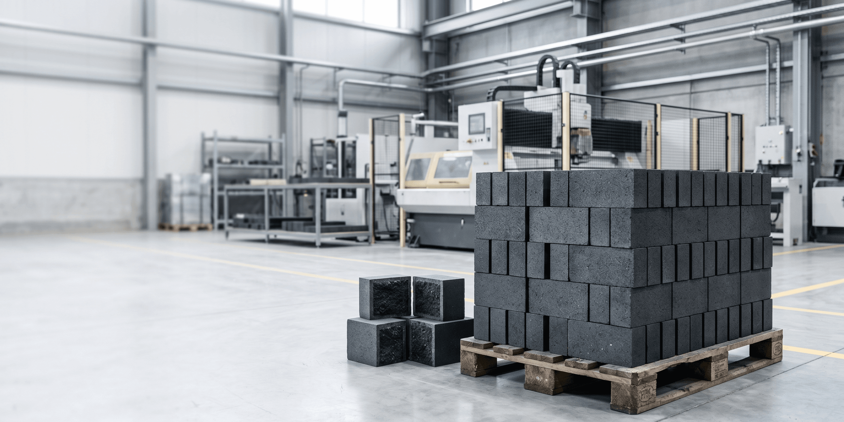
Diamond wire saw sectioning applied to magnesia-carbon refractory bricks from steelmaking vessel linings — clean cross-sections for metallurgical wear analysis, no graphite smearing, microstructure preserved.
Magnesia-carbon refractory is the lining material of choice for the working lining of basic oxygen furnaces, electric arc furnaces, and secondary metallurgy ladles. The material combines high-density magnesia grain — providing slag resistance and refractoriness — with graphite carbon in a resin bond matrix, which gives the composite its thermal shock resistance and thermal conductivity. The result is a lining material that can sustain repeated heating and cooling cycles, resist chemical attack from basic slags, and maintain structural integrity through the mechanical stresses of steel tapping and slag splashing.
Despite its performance characteristics, MgO-C lining is a consumable. The lining wears over each heat — magnesia grain dissolution into slag at the hot face, oxidation of the graphite phase, mechanical erosion at the slag line, and thermal spalling in the hotter zones. Managing lining life — knowing when to reline, where the lining is thinnest, and which wear mechanisms are dominant — is a significant operational and cost variable in steelmaking. The primary tool for understanding lining wear is post-mortem analysis: cutting used brick samples from the spent lining and examining the cross-section.
Cutting a used MgO-C brick for wear analysis sounds straightforward until you consider what the material actually is. Magnesia-carbon refractory is a composite: high-density periclase grains (MgO) set in a graphite-carbon matrix, bonded by a carbonised resin. The two phases have very different hardness and abrasion characteristics — the magnesia is harder than most cutting tools expect; the graphite is softer and has a tendency to smear under friction rather than cut cleanly.
Abrasive disc cutting on MgO-C produces two problems simultaneously. The intermittent loading and friction heat of disc cutting cause the graphite phase to smear across the cut face — graphite is a lubricant, and under the shear forces at a disc-abrasive interface, it spreads rather than cuts. The smeared graphite masks the actual microstructure of the magnesia grain and bond matrix. A cross-section prepared by disc cutting looks like a uniform grey surface — the graphite has been redistributed across the face, and the original phase distribution is no longer readable.
The second problem is thermal. Disc cutting generates heat at the cut face. In an already-used MgO-C brick, the resin bond has already been partially carbonised in service. Additional heat from cutting can cause further microstructural change in the near-surface zone of the sample — exactly the zone you are most interested in for wear analysis. A sample that has been thermally altered by the sectioning process cannot give an accurate picture of the wear state at the hot face.
The whole point of cutting a worn MgO-C brick is to read the microstructure at and behind the hot face: magnesia grain size and distribution in the wear zone, extent of graphite oxidation, depth of slag infiltration into the lining matrix, and the transition from worn hot face to relatively intact cold face. All of these features require a section that represents the actual material — not one where the cutting process has smeared, fractured, or thermally altered the zone of interest. Metallurgical examination of a poorly prepared section produces misleading results, which is worse than not cutting the sample at all.
Wear analysis on MgO-C typically involves a combination of techniques: visual examination of the cross-section macro-structure, optical microscopy, scanning electron microscopy with energy-dispersive X-ray analysis (SEM-EDX), and sometimes X-ray diffraction for phase identification. Each analytical technique has specific sample size and surface quality requirements. SEM samples have to fit within the chamber and mount holder. Optical microscopy requires a flat, polished surface that starts from a clean cut, not from a smeared or fractured one. The section dimensions are not arbitrary — they are determined by the downstream analytical requirements.
Diamond wire saw cutting addresses both of the primary problems with disc-abrasive sectioning of MgO-C: the graphite smearing problem and the thermal alteration problem.
The wire cuts by abrasion rather than shear. The cutting contact is distributed along the wire length and moves continuously — there is no intermittent impact, no concentrated friction zone, and no mechanism that applies the shear force that causes graphite to smear. On an MgO-C section, this means the graphite phase stays where it is. The cut face shows the actual phase distribution: magnesia grains, graphite flakes, and bond matrix in their original spatial relationship. The section is readable directly under reflected light without preparation that would itself alter the surface.
The thermal input at the cut face is also different. Wire cutting generates friction heat, but the heat is distributed and low compared to disc cutting — there is no localised high-temperature zone at the cut face. The carbonised resin bond in the near-surface zone of the used brick is not further altered by the sectioning process. The microstructure at the hot face — the one that records the wear history — is preserved.
Dimensional output from wire saw sectioning is controlled by the CNC program: section thickness, position relative to the hot face, and orientation relative to the brick geometry are all set in the program and executed consistently. This matters for wear analysis because the depth of features — slag infiltration front, graphite oxidation zone, magnesia dissolution front — is measured from the hot face, and that measurement is only meaningful if the section position relative to the face is known and consistent.
The MgO-C sections cut on this project were prepared for a combination of optical microscopy and SEM-EDX examination. A few specific observations:
Phase distribution at the hot face was clearly readable. The magnesia grain structure in the wear zone, the extent of graphite loss at and near the hot face, and the slag infiltration front were all identifiable in the sections without artefacts from the cutting process. The graphite phase was present in its original distribution — not smeared across the face.
The transition from hot face to cold face was preserved. The gradation from the heavily altered hot face zone through the partially affected mid-zone to the relatively intact cold face was continuous and representative in the section. This transition is what wear analysis is actually trying to characterise, and it requires a section that has not been thermally or mechanically disturbed by the cutting process.
Section dimensions matched the downstream analytical requirements. SEM sample preparation and optical microscopy mounting both proceeded without secondary resectioning. The one-cut approach — setting the target dimensions in the CNC program and cutting directly to the final sample size — avoided the additional handling and risk of microstructural damage that comes with multiple secondary cuts.
The conclusion that the analytical team reached was based on what the microstructure actually showed, not on an artefact of the preparation method. That is what a well-prepared section is supposed to deliver.
The refractory sampling and sectioning market is small and specialised. The people who need it — steelmaking process engineers, refractory engineers at steel producers, refractory manufacturer quality teams, and academic researchers studying wear mechanisms — know exactly what they need from a sample. They are not looking for a cutting service that will approximate the result; they are looking for one that will give them a section they can actually analyse.
Our approach to MgO-C sectioning is the same as for all refractory cutting work: parameters set for the material, not carried over from stone or metal. The graphite phase in MgO-C responds differently to cutting than either stone or pure ceramic, and the section quality on wear analysis samples is the output metric that matters. We have cut MgO-C sections for metallurgical examination and understand what the analytical requirements look like at the downstream end.
We do not publish sample-specific or project-specific details. If you have MgO-C lining samples from a converter, EAF, or ladle that require sectioning for wear analysis or process development work, Dinosaw Machinery is the conversation to start.
Contact us with your sample dimensions, the number of sections required, and the downstream analytical method you are preparing for.
 English
Get A Easy Solution
Chat Online
Hi, this is Lizzy from Dinosaw ( Not a Robot ). Which Machine ( model ) do you want? Please WhatsApp us now
Hello 👋 How can we help?